Notes on fixing a friend’s HP Compaq 8300 USDT SFF machine.
All of this was done around 23rd April 2022 and I’ve finally finished writing it all up.
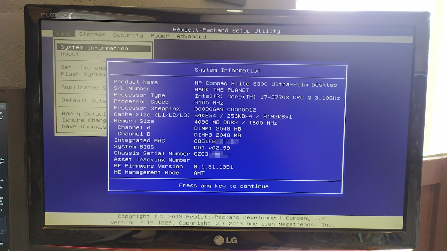
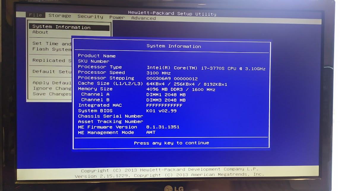
You can view the machine specifications on HP’s website, this particular machine was fitted with 4GB of RAM and a i7 processor.
Special thanks to the owner of this machine, my friend Hypn for doing a lot of the initial troubleshooting and for letting me take a soldering iron & hot air station to the motherboard for the more extreme repair.
The Problem
This machine would power up, and then after a minute or two max out all the fans but not boot. Occasionally it would beep that it had a corrupt BIOS and very, very infrequently it would boot.
I suspected this machine had similar problems to the Lenovo laptop I fixed in the past where the BIOS had gotten corrupt.
We tried all the HP recovery methods first but weren’t able to successfully do a BIOS recovery using any of the documented tools.
As this was a desktop machine it was relatively easy to open up and pull out the motherboard for inspection.
As usual I was looking for a flash chip that would store the BIOS.
BIOS Hardware Details
The flash chip is a Winbond 25Q128BVFG - Datasheet
Using the following flashrom command and the appropriately wired bus-pirate
sudo flashrom -p buspirate_spi:dev=/dev/ttyUSB0
chippy@pop-os:~$ sudo flashrom -p buspirate_spi:dev=/dev/ttyUSB0
flashrom v1.2 on Linux 5.16.15-76051615-generic (x86_64)
flashrom is free software, get the source code at [https://flashrom.org](https://flashrom.org/)

Using clock_gettime for delay loops (clk_id: 1, resolution: 1ns).
Found Winbond flash chip "W25Q128.V" (16384 kB, SPI) on buspirate_spi.
No operations were specified.
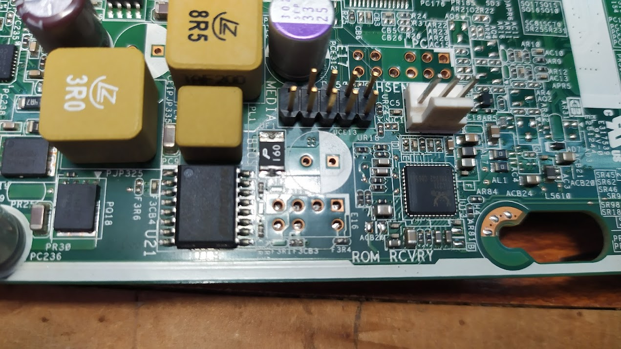
ROM RCVRY Header
Unpopulated ROM RCVRY Header on the motherboard.
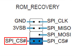
Pinout of the ROM RCVRY header
The SPI_CS# pin highlighted in red is the one going to the chip and the one that you need to use if you want to interact with the chip.
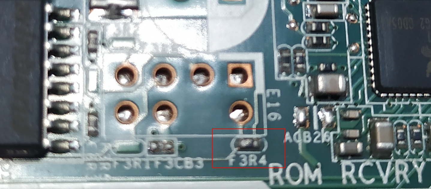
On the motherboard is a 0Ω resistor (F3R4) that is being used as a jumper across the two CS (chip select) pins. In order to use the header you need to remove the resistor off the board and instead use a traditional jumper across the pins.
Notes on bus-pirate and hooking it up.
Pin-out of the bus-pirate header 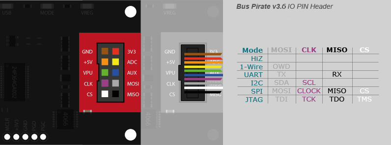
Dumping the BIOS
Connecting the bus-pirate to the ROM RCVRY header and attempt to dump the BIOS using the following command.
sudo flashrom -p buspirate_spi:dev=/dev/ttyUSB0 -r hp-bios.bin
In order to get a clean dump of the BIOS you need to have the computer plugged in (so that the 3.3v standby LED on the motherboard is on) but the machine can’t be powered on.
Useful tool for doing binary diff on Linux vbindiff
Flashing the BIOS - Attempt 1
⚠️ Warning
All of "Attempt 1" turned out to be wrong, but I've left it here for future reference.
See below for more info on what worked.
Using the following command (from the coreboot flashing page) we attempt to re-flash an official HP BIOS. This command downloads the current BIOS then replaces only the BIOS part of the image and flashes it back to the flash chip.
flashrom --ifd -i bios -w K01_0290.bin -p buspirate_spi:dev=/dev/ttyUSB0
📝 Note
Unfortunately this didn't work, the ROM RCVRY header doesn't expose the /WP pin of the flash chip.
This means that you can't put the chip into write enabled mode. Various docs online hint at the chip also having certain sections of the memory write protected via other protection methods.
Additional notes
Early on in an attempt to get a good dump of the chip I lifted pin 2 (VCC) in the hopes that I could power just the flash chip to get a clean dump. This didn’t work, I suspect because some of the external circuitry between the chip and the ROM RCVRY header also requires the same VCC (3.3v) power supply.
To try to get the flash chip writable I attempted shorting the WP pin to the VCC ping but as WP is pulled low (direct to ground it appears) all it did was create a big spark.
As the original HP software is able to write to the chip I assume there is some kind of write enable that’s controlled via software.
Flashing the BIOS to alternative flash chip - Attempt 2
⚠️ Warning
"Attempt 2" turned out to be wrong as well, but we did learn things. I've left it here for future reference.
See below for more info on what worked.
Not all the flash pins are exposed via ROM RCVRY header which means we can’t re-flash the chip without desoldering it. (Not sure if we could program it with a chip clip)
New idea is to use a breakout board with a W25Q128 chip on it and then flash it with a clean BIOS image (or a patched version of the original dump) and connect it to the ROM RCVRY header, hopefully the motherboard will boot this new BIOS instead of the original.
This assumes it doesn’t check the flash chips serial (is that even a thing?) and that it’s not using the quad SPI features of the chip or any other “special” features that it may have turned on.
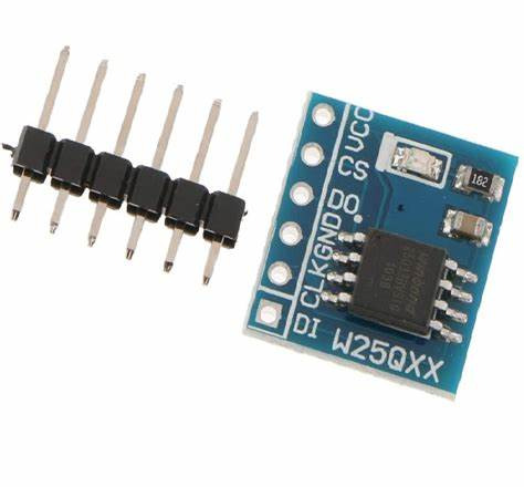 W25Q128 Flash Storage Module - SPI Interface (purchased from BotShop however they no longer have them.)
If it boots this then it should be possible to swap the CS pins so that they go to the original chip and then program it once the machine is booted.
Wiring it all up
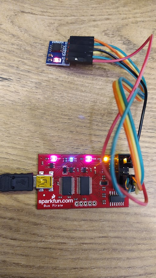 With the chip attached to the bus pirate and following command
 sudo flashrom -p buspirate_spi:dev=/dev/ttyUSB0
I get this output
chippy@fire:~$ sudo flashrom -p buspirate_spi:dev=/dev/ttyUSB0
flashrom v1.2 on Linux 5.16.19-76051619-generic (x86_64)
flashrom is free software, get the source code at https://flashrom.org

Using clock_gettime for delay loops (clk_id: 1, resolution: 1ns).
Found Winbond flash chip "W25Q128.V..M" (16384 kB, SPI) on buspirate_spi.
No operations were specified.
Next step is writing the original dump of the firmware from the HP to this new chip with the following command.
sudo flashrom -w hp7.bin -p buspirate_spi:dev=/dev/ttyUSB0
This ended up hanging on the erase step and it never went any further. flashrom was not able to write to the chip, or perhaps better stated was not able to erase the chip.
Switching gears
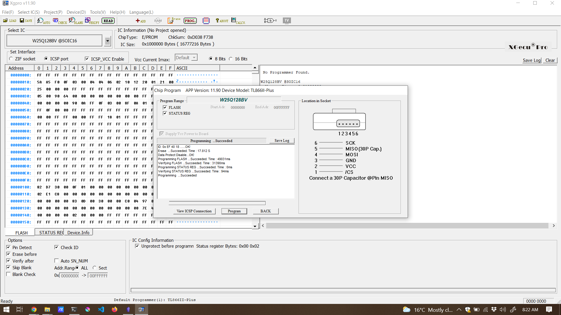
Not being able to write to the flash chip with the bus pirate and flashrom I decided to try my TL866II with a SOIC8 chip clip on the little boards we purchased.
Xgpro v11.90 software doesn’t have an entry for the chip on these external boards but appeared to work fine with another W25Q128 profile selected and Check ID turned off.
With this I was able to read, erase and write to the chips and finally was able to write a clean BIOS image to the external chip.
Continuing on
With the external flash chip wired to the ROM_RCVRY header I attempted to boot the machine.
Nothing happened, the machine continued to act just as if the CS jumper wasn’t installed which meant it wasn’t seeing the external chip.
Why didn’t it work? - Learning from failure
It was originally a long shot to try booting off an external BIOS chip. I suspect this didn’t work because the motherboard is actually using QUAD Mode (which is an option on the SOIC16 chip) and not available on the SOIC8 version I have on the breakout boards or via the ROM_RCVRY header.
What I did learn from this attempt was that the bus pirate + flashrom seems to not be able to write to the W25Q128 (or any of the W25Qxx chips), this would explain why my original attempt to write to the chip on the motherboard failed.
Another thing I discovered while playing with the TL866II was that its possible to program a chip using the ICSP header on the programmer allowing it to program something in place.
Using the TL866II programmer + ICSP header to program the BIOS flash chip on HP motherboard - Attempt 3
As mentioned, it would appear from the previous attempt that either flashrom or the bus pirate are not able to write to these W25Qxx (tried both a 128Mbit and 64Mbit variants) flash chips.
Now that I know I can use the ICSP header to program these chips, I could maybe program the chip on the motherboard that way?
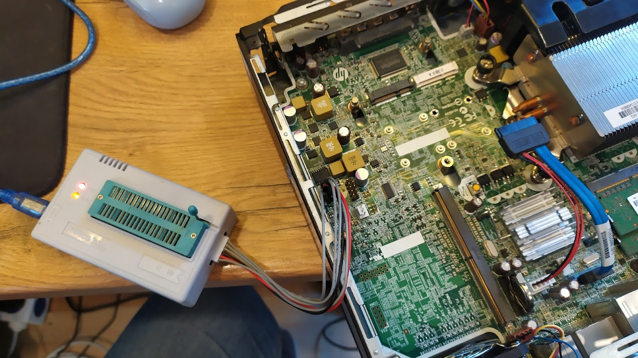
Writing to the BIOS chip
Using the TL866II programmer and the ICSP header I was able to program the BIOS chip in the machine. It requires the computer to have power but not be switched on and it appears turning on the ICSP_VCC_Enable option might make a difference to getting a reliable write.
Next I took the K01_0290.BIN image and wrote it to the chip, it required multiple attempts until it successfully verified.
After the successful programming of the chip, I re-enabled the BIOS chip by putting the CS jumper back and powered it up.
The machine booted on the first try. (Although it does appear that it doesn’t boot reliably with things plugged into the ROM_RCVRY header)
Obviously the machine has no serial no, model no etc but it boots into the BIOS which is a massive improvement.
Next Step - Patch the BIOS with the old details
Now that we can reliably write to the BIOS chip we need to get some of the original information back, in particular the MAC address, UUID of the machine, Serial No etc.
⚠️ Warning
I've not figured out a reliable way to do this, what follows below is how I did it but I'm sure there must be a better way.
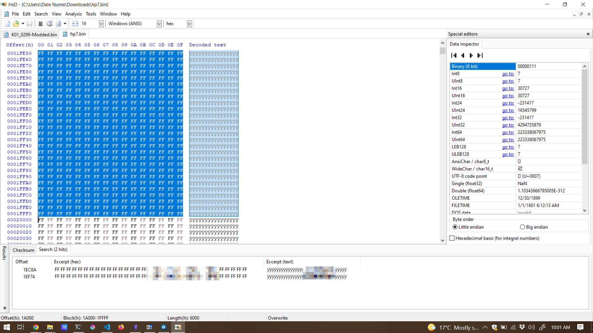
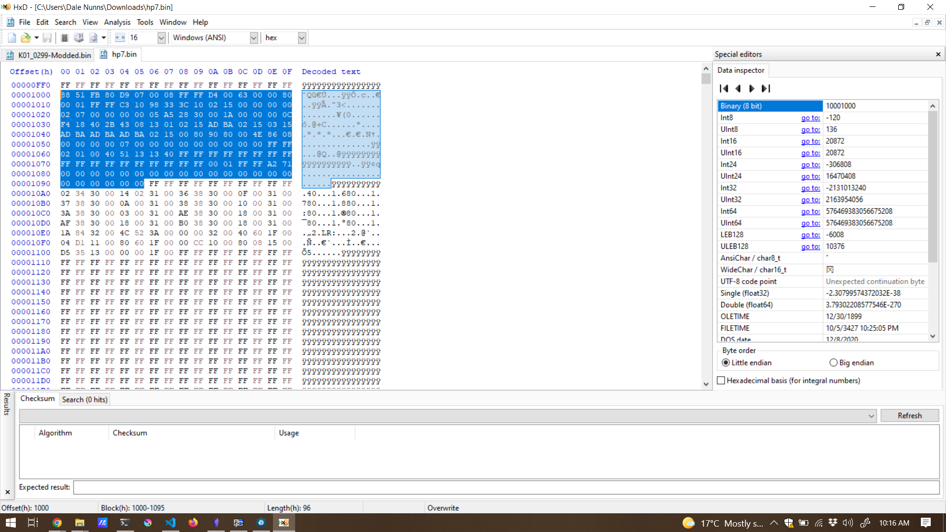
I started with a clean BIOS image K01_0299.BIN then went through the original dumped BIOS image trying to find all the values I was looking for.
In the end I copied the following sections from the dumped BIOS to the new modified K01_0299 image.
0x001000 - 0x001095
0x01A000 - 0x01FFFF
Copied the following block from the original dump.
Another section
Booting the new BIOS
These patches got the MAC address set for the onboard adapter but unfortunately weren’t enough to get the rest of the details restored.
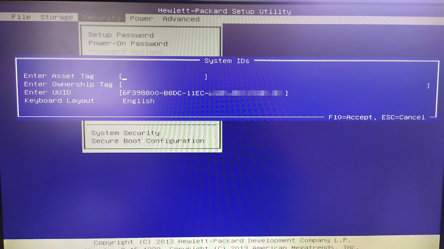
Once written and booted you can use CTRL+A in the BIOS to enable advanced mode (the BIOS is fully unlocked) and then go change all your details in the Security Id’s section under security
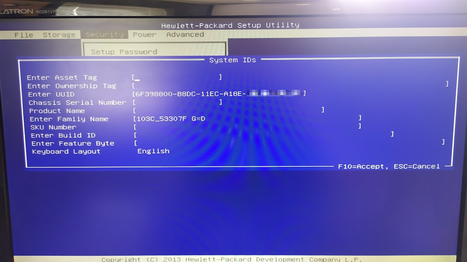
I got lucky and found all the additional information on official HP stickers on the outside of the machine so that I could add them all back into the configuration.